



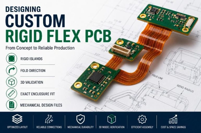
Electronic products continue to become smaller, lighter, and more mechanically complex while delivering higher performance than ever before. Meeting these demands often requires more than simply reducing PCB dimensions. Engineers must also optimise how electronic assemblies fit within the product enclosure while maintaining long term mechanical and electrical reliability.
A well designed custom rigid flex PCB can replace multiple rigid boards, connectors, and cable assemblies with a single integrated circuit structure. This approach simplifies assembly, reduces interconnection failures, and allows designers greater flexibility when working with compact or irregular product geometries.
Successful rigid flex development depends on careful planning during the earliest design stages. Mechanical constraints, fold direction, bend sequence, rigid island placement, and three dimensional validation all influence whether a design can be manufactured consistently and perform reliably throughout its service life.
This guide explains the most important engineering considerations involved in designing and manufacturing custom rigid flex PCBs.
Why Custom Rigid Flex Designs Require Early Planning
Unlike conventional rigid PCBs, rigid flex circuits combine rigid and flexible sections into one interconnected structure.
Because both electrical and mechanical requirements must be satisfied simultaneously, layout decisions cannot be made independently from enclosure design.
During the initial concept stage, engineering teams should evaluate:
- Product dimensions
- Assembly sequence
- Connector locations
- Mechanical movement
- Service accessibility
- Manufacturing constraints
Resolving these considerations early reduces design revisions later in development while improving manufacturing efficiency.
Designing Rigid Islands
Rigid islands provide structural support for components that cannot be mounted directly onto flexible circuitry.
These rigid sections typically accommodate:
- Integrated circuits
- Connectors
- Power components
- Shielded modules
- High density BGAs
When positioning rigid islands, designers should consider:
- Component spacing
- Heat generation
- Mechanical support
- Routing accessibility
- Assembly processes
Poor placement can increase stress within nearby flex regions or complicate enclosure assembly.
Balancing electrical routing with mechanical stability helps improve both manufacturability and long term product reliability.
Planning Fold Direction
Fold direction is one of the most important mechanical considerations in rigid flex PCB design.
The flexible section should bend naturally according to the intended product assembly rather than being forced into position during installation.
Engineers should define:
- Primary fold direction
- Bend locations
- Assembly orientation
- Installation sequence
- Service access
Incorrect fold planning may place unnecessary stress on conductors, coverlay materials, or solder joints during product assembly.
Mechanical and electrical teams should review folding requirements together before finalising the PCB layout.
Bend Sequence and Assembly Order
Products containing multiple folds often require a carefully defined bend sequence.
The order in which each bend is performed can influence:
- Mechanical clearance
- Component accessibility
- Assembly tooling
- Cable routing
- Manufacturing repeatability
Documenting the intended bend sequence provides manufacturing teams with clear guidance while reducing the possibility of assembly errors.
For products assembled in high volumes, standardised bend procedures also improve production consistency.
Enclosure Fit Should Be Verified Early
Rigid flex PCBs are often selected because they simplify integration within compact product enclosures.
However, successful enclosure integration depends on more than simply matching board dimensions.
Designers should evaluate:
- Internal clearance
- Mounting points
- Connector alignment
- Cable movement
- Fold geometry
- Fastener locations
Even minor dimensional conflicts can require significant redesign after tooling has been completed.
Reviewing enclosure compatibility early helps reduce project risk while shortening development time.
Three Dimensional Validation
Traditional two dimensional PCB layouts cannot always reveal potential mechanical conflicts within complex products.
Three dimensional validation allows engineering teams to evaluate how the rigid flex assembly behaves after folding.
Important areas to verify include:
- Fold geometry
- Component interference
- Connector alignment
- Bend clearance
- Housing integration
- Mechanical tolerances
Modern CAD systems allow designers to simulate folded configurations before production begins.
Identifying mechanical issues digitally is generally far less expensive than correcting them after prototype fabrication.
Mechanical Design Files
Rigid flex PCB manufacturing depends on more than Gerber files alone.
Comprehensive mechanical documentation helps manufacturers understand how the finished assembly should function within the product.
Useful design files include:
- Mechanical drawings
- STEP models
- DXF outlines
- Stackup documentation
- Bend location drawings
- Assembly instructions
Providing complete engineering documentation reduces interpretation errors while improving communication between design and manufacturing teams.
Design Review Checklist
Before releasing a custom rigid flex PCB design for fabrication, engineering teams should verify the following items.
| Design Area | Verification |
| Rigid island placement | Supports component layout and assembly |
| Fold direction | Matches intended product installation |
| Bend sequence | Documented for manufacturing |
| Enclosure fit | Verified using mechanical models |
| 3D validation | Completed before prototype release |
| Mechanical files | STEP, DXF, drawings provided |
| Component clearance | Confirmed after folding |
| Routing | Supports both electrical and mechanical requirements |
Using a structured review process helps identify potential design issues before they become costly manufacturing changes.
Material Selection for Long Term Reliability
Selecting appropriate materials is one of the most important decisions in custom rigid flex PCB development. Material choice influences not only electrical performance but also bend reliability, thermal stability, and manufacturing consistency.
Rigid flex constructions typically combine FR-4 laminates with flexible polyimide substrates. These materials must work together throughout multiple lamination cycles while maintaining dimensional stability during fabrication and product operation.
Engineers should evaluate:
- Polyimide thickness
- Copper weight
- Dielectric properties
- Glass transition temperature
- Thermal expansion characteristics
- Material compatibility
Choosing materials that match the mechanical and environmental requirements of the application helps improve both manufacturing yield and product reliability.
Design for Manufacturability Review
A comprehensive Design for Manufacturability (DFM) review helps identify production challenges before fabrication begins.
Rigid flex PCBs require DFM evaluations that consider both electrical layout and mechanical behaviour.
Typical review areas include:
- Stackup construction
- Rigid island placement
- Fold direction
- Bend sequence
- Copper balancing
- Component placement
- Coverlay openings
- Manufacturing tolerances
- Panel utilisation
Early collaboration between engineering and manufacturing teams often reduces prototype revisions while improving production efficiency.
Inspection and Quality Verification
Inspection plays an essential role throughout rigid flex PCB manufacturing because many internal features cannot be evaluated after assembly.
Rather than relying only on final inspection, experienced manufacturers verify quality during multiple production stages.
Common inspection procedures include:
- Automated Optical Inspection (AOI)
- X ray inspection
- Cross section analysis
- Electrical continuity testing
- Dimensional verification
- Visual inspection of flexible regions
- Lamination quality assessment
These inspections help verify layer alignment, copper integrity, dielectric thickness, and overall manufacturing consistency.
A manufacturer should also be able to explain how inspection data supports continuous process improvement rather than simply listing available equipment.
Reliability Testing
Rigid flex circuits often operate in environments where mechanical movement, vibration, and thermal cycling are common.
Manufacturers should therefore validate that finished products meet the reliability requirements of their intended application.
Typical evaluations include:
- Bend performance testing
- Thermal cycling
- Mechanical durability assessment
- Electrical continuity verification
- Environmental testing
- Visual inspection after mechanical stress
The level of testing depends on product requirements, operating conditions, and applicable industry standards.
Considering reliability during both design and manufacturing helps reduce field failures while improving product life expectancy.
Prototype to Production Transition
A successful engineering prototype represents only one stage of product development.
Manufacturers should demonstrate how prototype processes transition into repeatable production while maintaining consistent quality.
Useful questions include:
- How are engineering revisions managed?
- What manufacturing documentation accompanies production?
- How is material traceability maintained?
- Are inspection procedures identical for prototype and production?
- How are process improvements documented?
Manufacturers with established production control systems are generally better positioned to deliver consistent results throughout the product lifecycle.
Common Design Mistakes
Several design decisions can unnecessarily increase manufacturing complexity or reduce long term reliability.
Common issues include:
- Positioning rigid islands without considering assembly access
- Defining unrealistic fold directions
- Ignoring bend sequence during layout
- Delaying enclosure validation until prototype assembly
- Providing incomplete mechanical documentation
- Skipping three dimensional design verification
- Neglecting Design for Manufacturability review
Identifying these issues early allows engineering teams to make cost effective improvements before fabrication begins.
Engineering Review Checklist
Before releasing a custom rigid flex PCB for manufacturing, engineering teams should verify that all critical mechanical and electrical considerations have been reviewed.
| Design Area | Verification |
| Material selection | Appropriate for electrical and mechanical requirements |
| Rigid islands | Optimised for assembly and structural support |
| Fold direction | Matches product installation sequence |
| Bend sequence | Clearly documented |
| Enclosure fit | Verified using three dimensional models |
| Mechanical documentation | STEP models, drawings, DXF files provided |
| Inspection requirements | Defined before production |
| DFM review | Completed with manufacturing team |
| Prototype planning | Supports transition to production |
Using a structured engineering review helps minimise design revisions while improving manufacturing consistency.
Final Thoughts
Custom rigid flex PCB development requires close coordination between electrical, mechanical, and manufacturing disciplines. Decisions involving rigid island placement, fold direction, bend sequence, enclosure integration, material selection, and three dimensional validation all influence whether a design can be manufactured efficiently and perform reliably in service.
A successful project begins with thoughtful planning rather than solving mechanical challenges after the PCB layout has been completed. Early Design for Manufacturability reviews, complete mechanical documentation, and comprehensive engineering validation help reduce development risks while supporting a smoother transition from prototype to production.
For organisations developing advanced electronic products, fast turn rigid flex PCB manufacturing services provide engineering support throughout the design, prototype, and production process. As with any complex PCB project, manufacturing methods, achievable lead times, and material recommendations should always be confirmed after reviewing the specific board design, enclosure constraints, production quantity, and testing requirements.
By combining careful mechanical planning with proven manufacturing practices, engineering teams can create rigid flex PCB solutions that improve assembly efficiency, reduce interconnection complexity, and deliver dependable performance throughout the product’s operational life.