



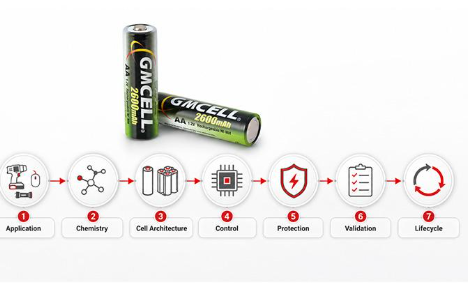
Learn how chemistry selection, electrical architecture, charging control, thermal behavior, mechanical protection, testing, and manufacturing quality work together to create safer and more dependable industrial battery systems.
- Chemistry Selection
- Cell Architecture
- Thermal Control
- Mechanical Protection
- Testing & Validation
Industrial battery reliability depends on the complete interaction between chemistry, electrical design, thermal conditions, structural protection, and lifecycle control.
Why Industrial Battery Design Requires a Different Approach
Consumer batteries are often evaluated by energy density, runtime, weight, and charging speed. Your priorities may be very different when selecting a battery for industrial equipment. The battery may need to remain on standby for months, operate under continuous vibration, support repeated peak loads, tolerate changing temperatures, or continue supplying power when equipment safety, process continuity, and data integrity depend on it. In these conditions, capacity and energy density alone cannot tell you whether a battery will remain reliable throughout its intended service life.
Reliable industrial battery design therefore requires more than choosing a cell with an attractive datasheet. You need to consider how the battery chemistry responds to the real load profile, how consistently individual cells perform, how charging is controlled, where heat accumulates, and how the pack is protected from vibration, moisture, electrical faults, and mechanical stress. Protection circuits, monitoring systems, validation testing, manufacturing consistency, and maintenance planning must all support the same operating requirements.
This guide explains the core design principles that can help you improve battery service life, reduce unexpected failures, and create safer power systems. It applies these principles across embedded devices, backup systems, industrial controllers, medical equipment, mobile machinery, and large energy storage installations, while showing how design priorities change with battery chemistry, equipment risk, and system scale.
The Core Principles at a Glance
Before comparing individual battery specifications, use these seven principles to evaluate the complete power system. Each principle addresses a different source of premature aging, unsafe operation, or unexpected equipment failure.
Define the Application First
Establish voltage, load, runtime, temperature, maintenance, and failure-risk requirements before selecting a battery chemistry.
Match Chemistry and Cell Format
Select the chemistry and physical cell format that best fit your operating profile, space, weight, safety, and service-life priorities.
Design Around Real Loads
Configure cells, wiring, connectors, fuses, and protection devices around actual continuous currents, pulse loads, and voltage limits.
Use Chemistry-Specific Control
Match charging, termination, monitoring, balancing, and fault protection to the behavior of the selected battery chemistry.
Control Temperature Variation
Prevent excessive heat, low-temperature performance loss, and uneven cell aging by managing both temperature and temperature uniformity.
Contain Mechanical and System Faults
Protect cells, connections, and insulation from vibration, shock, moisture, short circuits, and failures that could spread through the pack.
Validate and Manage the Complete Lifecycle
Test the battery under realistic operating conditions, maintain production consistency, preserve traceability, and plan for inspection, replacement, and end-of-life handling.
The Industrial Battery Design Path
Each decision affects the next stage, so reliability must be managed as one connected engineering process.
Application → Chemistry → Cell Architecture → Control → Protection → Validation → Lifecycle
What Long-Term Reliability Means in Industrial Battery Design
When you evaluate an industrial battery system, reliability does not mean that the battery will retain its original performance forever. Every battery ages through chemical reactions, repeated charging, storage, temperature exposure, and electrical stress. The practical question is whether that aging remains gradual, measurable, and compatible with the service life of your equipment.
Performance Must Remain Predictable
You need to understand how calendar life, cycle life, capacity retention, voltage stability, and internal resistance are expected to change over time. A battery may still show acceptable capacity during a low-current test but fail to support your equipment when a peak load causes the voltage to collapse.
Charge retention and self-discharge are equally important in standby power applications. A battery that operates correctly immediately after charging may not be suitable if it cannot deliver the required energy after remaining unused for several months.
Aging Must Be Detectable and Manageable
Reliable design gives you enough warning to inspect, service, or replace the battery before it loses a critical function. This may involve tracking runtime, voltage under load, internal resistance, temperature history, fault records, or scheduled maintenance intervals.
Replacement availability also matters. A battery cannot support long-term equipment reliability if a compatible pack, connector, voltage, or approved replacement specification will no longer be available when the original unit reaches the end of its service life.
A reliable industrial battery is not one that avoids all aging. It is one whose aging remains predictable, detectable, and manageable throughout the intended service life.
What Uncontrolled Battery Aging Can Look Like
A backup battery remains on standby for months but cannot start the equipment when primary power fails.
One weak cell limits a complete series-connected pack and causes premature shutdown.
Pack voltage drops sharply when motors, radios, pumps, or actuators create a peak load.
Incorrect charge termination causes repeated overcharging, heat generation, and accelerated capacity loss.
Vibration gradually loosens a weld, cable, terminal, or connector and increases electrical resistance.
Continuous exposure to high temperature shortens both capacity life and calendar life.
Start With the Application and Failure Consequences
Your first design question should not be, “Which battery chemistry should I use?” Start by defining what the equipment actually needs from its power source. A battery selected before the load, environment, charging method, and service expectations are understood may meet its datasheet specifications while still performing poorly inside the final equipment.
Begin with the electrical profile. Confirm the nominal voltage, acceptable operating-voltage range, continuous current, peak current, pulse duration, required runtime, allowable voltage drop, and standby power requirements. A device with a low average current may still require a battery capable of supporting short, repeated high-current pulses without triggering a reset or low-voltage shutdown.
Electrical Profile
Define voltage limits, continuous current, peak demand, pulse duration, runtime, voltage drop, and charging power.
Operating Environment
Evaluate operating and storage temperature, humidity, dust, vibration, shock, orientation, and outdoor exposure.
Lifecycle Expectations
Set targets for cycle life, calendar life, charging frequency, standby duration, maintenance, and replacement availability.
Failure Consequences
Determine whether battery failure causes inconvenience, lost data, process interruption, equipment damage, or a safety hazard.
What happens when the battery fails?
The answer determines how much redundancy, monitoring, testing, protection, and maintenance your design requires. A battery failure in a handheld measuring instrument may only stop a task. In an industrial controller, it may erase parameters or interrupt a process. In medical, security, communications, or large energy storage systems, the same failure may have more serious operational or safety consequences.
| Requirement | Questions You Need to Answer |
|---|---|
| Voltage | What nominal, maximum, and minimum voltage does your device require? |
| Load | What are the continuous current, peak-current demand, and pulse duration? |
| Runtime | How long must the equipment operate between charges or after primary power is lost? |
| Environment | What temperature, vibration, moisture, dust, shock, and installation conditions are expected? |
| Maintenance | Can the battery be inspected, tested, serviced, or replaced at regular intervals? |
| Failure Risk | What operational, financial, data, equipment, or safety consequences follow a sudden loss of battery power? |
Select the Battery Chemistry Around the Operating Profile
No battery chemistry is universally best for industrial equipment. The correct choice depends on the electrical load, charging conditions, available space, maintenance strategy, operating temperature, safety requirements, and consequences of failure. Comparing energy density alone may lead you toward a battery that looks attractive on paper but introduces unnecessary charging complexity, thermal risk, maintenance demands, or lifecycle cost.
Evaluate each chemistry as part of a complete system. The cell voltage, discharge behavior, charger, protection components, monitoring requirements, mechanical enclosure, service process, and replacement strategy all affect whether the final battery will perform reliably inside your equipment.
Nickel-Metal Hydride
Nickel-metal hydride is a mature rechargeable chemistry with a long history in industrial equipment, embedded electronics, backup devices, emergency systems, medical products, and security equipment. A typical NiMH cell has a nominal voltage of 1.2V and can be assembled in series to meet different equipment-voltage requirements.
For equipment that values proven safety, predictable voltage behavior, rechargeable operation, and long-term serviceability, a properly specified NiMH Battery can remain a practical choice for industrial controllers, medical equipment, backup systems, and embedded devices.
NiMH may also allow a less complex pack architecture than many multi-cell lithium-ion systems, particularly in smaller applications. However, simpler does not mean uncontrolled. The charger must use an appropriate current and reliable termination method, which may include negative delta-V detection, temperature rise, dT/dt monitoring, and a safety timer. Temperature sensing becomes particularly important when the battery remains connected to a charger for long periods.
The trade-offs are lower energy density than lithium-ion and generally higher self-discharge. You should evaluate self-discharge using the actual cell type, standby duration, storage temperature, and recharge schedule rather than assuming one value represents every NiMH design.
Lithium-Ion
Lithium-ion is often selected when your equipment needs high energy density, low weight, compact dimensions, or extended runtime. Its relatively low self-discharge can also support portable and intermittently used equipment where stored energy must remain available between operating periods.
These advantages require precise charging and protection. Lithium-ion cells typically use constant-current and constant-voltage charging, with strict limits for charge voltage, discharge voltage, current, and temperature. A multi-cell series pack commonly requires individual cell monitoring, balancing, or both to prevent one cell from reaching an unsafe limit before the others.
Thermal design should reflect the selected lithium-ion chemistry, cell format, power level, enclosure, and system scale. A compact portable pack may need temperature sensing and passive heat dissipation, while a high-power industrial pack or energy storage installation may require active cooling, module isolation, and more advanced fault management.
Lithium Iron Phosphate
Lithium iron phosphate, commonly identified as LiFePO4 or LFP, is valued for thermal stability and long cycle-life potential. It is widely considered for stationary storage, industrial mobility, material-handling equipment, backup power, and other applications where long-term cycling and thermal behavior may be more important than achieving the highest possible energy density.
LFP is still a lithium-ion chemistry and requires a compatible charger, appropriate voltage protection, current control, temperature monitoring, and a suitable BMS for multi-cell systems. Its energy density is generally lower than that of some other lithium-ion variants, which can affect pack size and weight.
You should not treat LFP as the automatic answer for every industrial application. Its suitability depends on system voltage, available installation space, mass limits, current demand, charger compatibility, service requirements, and total system cost.
Lead-Acid
Lead-acid remains relevant where mature infrastructure, low initial cost, established charging systems, and predictable standby operation are important. It is commonly found in fixed backup power, uninterruptible power supplies, alarm systems, emergency equipment, and some industrial vehicles.
Its disadvantages include high weight, relatively low energy density, and reduced service life when repeatedly exposed to deep discharge or extended undercharging. Installation space, orientation, ventilation, inspection access, and replacement handling may also affect the complete system design.
Primary Lithium
Primary lithium batteries are useful when your equipment requires long storage life, low self-discharge, and minimal maintenance without recharging. Typical applications include remote sensors, metering equipment, tracking systems, memory backup, monitoring devices, and other products that may operate unattended for extended periods.
Because these batteries are not rechargeable, they are unsuitable for devices that require frequent energy replenishment or repeated deep-discharge cycles. You must also evaluate pulse-current capability, passivation behavior where relevant, transport requirements, replacement access, and safe end-of-life handling.
Your design decision: Select the chemistry whose voltage behavior, charging method, temperature response, maintenance needs, and protection architecture best match the equipment. The most reliable choice is not necessarily the battery with the highest capacity or energy density.
Choose the Cell Format and Packaging Architecture
Battery chemistry determines fundamental characteristics such as nominal voltage, energy density, charging behavior, and temperature response. The physical cell format determines how effectively those characteristics can be used inside your equipment. Your choice affects mechanical strength, space utilization, heat-transfer paths, assembly complexity, replacement options, production consistency, and the way a fault may spread through the battery pack.
You should therefore evaluate chemistry and cell format as two separate but connected decisions. A cylindrical NiMH cell and a cylindrical lithium-ion cell may share a similar external shape, but they require different charging, protection, monitoring, and safety strategies. Likewise, cells using the same chemistry may behave differently when assembled as cylindrical, prismatic, or pouch-based systems.
Cylindrical Cells
Cylindrical cells are highly standardized and usually protected by a rigid metal casing. Their shape provides useful mechanical strength and exposes a relatively large external surface area for heat transfer. Standard sizes can also simplify sourcing, automated production, replacement, and long-term product support.
They are common in NiMH battery packs, lithium-ion power packs, backup equipment, medical products, handheld instruments, and industrial electronics. However, assembling many cylindrical cells creates additional welds, busbars, holders, and electrical connections. Each connection must be designed to withstand current, vibration, heat, and repeated use.
Prismatic Cells
Prismatic cells can use rectangular installation space efficiently and reduce the number of individual cells required in a higher-capacity module. This can simplify some interconnections and make them attractive for industrial mobility, stationary storage, large backup systems, and other applications where higher capacity is required.
You must still manage mechanical restraint, cell expansion, terminal loading, heat distribution, and module compression carefully. Large flat surfaces do not automatically guarantee uniform cooling, and insufficient support may allow movement or swelling to place stress on terminals and the surrounding enclosure.
Pouch Cells
Pouch cells offer low packaging weight and flexible dimensions, allowing you to use thin or irregular spaces more efficiently. They are useful when portable industrial equipment requires a compact battery with a high ratio of active material to packaging weight.
Because the external pouch provides less structural protection than a rigid cylindrical or prismatic casing, the final battery pack must supply adequate support. Your design should protect the cell from puncture, compression, bending, edge damage, uncontrolled swelling, and contact with sharp enclosure components.
Configure Voltage, Capacity, and Current Around the Load
Connecting cells in series increases pack voltage, while connecting cells in parallel increases available capacity and current capability. The configuration must match your equipment’s voltage window, runtime requirement, peak load, and charging architecture.
Series Connection: Use series-connected cells when you need a higher operating voltage. Each additional cell also introduces another point where capacity, resistance, or self-discharge mismatch can affect the complete string.
Parallel Connection: Use parallel-connected cells when you need more capacity or current capability. Current sharing, conductor resistance, cell consistency, and protection must remain balanced between parallel paths.
More Cells, More Variables: A larger pack creates more welds, connectors, thermal interactions, and potential mismatch points. Pack complexity should increase only when the application genuinely requires it.
Compare NiMH and Lithium-Ion as Complete Engineering Systems
Energy density is important, but it is only one part of your design decision. A lighter battery with longer runtime may also require more precise charging, individual cell monitoring, balancing, and stricter protection. A heavier battery with moderate energy density may provide a simpler maintenance path or greater tolerance in a particular operating environment.
A practical nimh battery vs lithium ion comparison must consider charging architecture, temperature behavior, maintenance access, protection requirements, expected service life, and the consequences of battery failure—not energy density alone.
| Design Consideration | NiMH | Lithium-Ion |
|---|---|---|
| Energy Density | Moderate | High |
| Pack Weight | Generally higher for the same stored energy | Generally lower |
| Charging Method | Constant current with voltage, temperature, and timer-based termination controls | Precise constant-current and constant-voltage charging |
| Monitoring Complexity | Often simpler in small and medium packs | Usually more extensive, especially in series-connected systems |
| Cell Balancing | Not normally managed in the same way as lithium-ion balancing | Commonly required in multi-cell series packs |
| Self-Discharge | Generally higher and cell-design dependent | Generally lower |
| Overcharge Tolerance | More tolerant under appropriately controlled conditions | Requires strict charge-voltage protection |
| Thermal Runaway Concern | Lower | Depends on chemistry, cell design, power level, and system controls |
| Embedded Backup Use | Well established in suitable applications | Suitable when charging and protection are correctly designed |
| Typical Design Priority | Stability, proven operation, and serviceability | Energy density, compact size, low weight, and runtime |
When NiMH May Fit Your Priorities
NiMH may suit your equipment when you prioritize mature rechargeable technology, predictable operation, manageable charging, established replacement formats, and reliable performance in backup power, controllers, medical devices, security equipment, or embedded systems.
When Lithium-Ion May Fit Your Priorities
Lithium-ion may be the stronger option when your equipment requires high energy density, reduced weight, compact dimensions, low self-discharge, or longer operation between charges—and can support the required charging, protection, and monitoring architecture.
The better chemistry is the one that fits your equipment—not the one with the highest value in a single datasheet category.
Engineer Cell Consistency and Electrical Architecture
A battery pack does not perform like an average of all its cells. In a series-connected pack, the weakest cell can reach its charge or discharge limit before the others, reducing usable capacity and causing the equipment to shut down earlier than expected. In a parallel group, differences in resistance and charge level can create uneven current sharing and accelerated aging.
For that reason, reliable pack design depends on both cell matching and a low-resistance, mechanically stable electrical path. High-quality cells cannot deliver their expected performance when they are connected through undersized wiring, inconsistent welds, high-resistance terminals, or unstable connectors.
Match Cells Before Building the Pack
Cells with the same printed model number may still differ slightly because of manufacturing tolerances, storage history, and aging. Before assembly, you should evaluate the characteristics that directly affect pack balance and long-term performance.
Capacity matching: helps cells reach similar charge and discharge points.
Open-circuit voltage: can reveal differences in state of charge or abnormal cells.
Internal resistance: affects heat generation and voltage drop under load.
Self-discharge: helps prevent one cell from becoming weaker during standby.
Charge acceptance: reduces uneven charging and temperature differences.
Batch and aging consistency: supports more predictable lifecycle performance.
Design a Stable Electrical Path
Every conductor and connection between the cells and your equipment adds resistance. This resistance consumes energy, generates heat, and causes voltage drop. The effect becomes more significant in high-current industrial equipment, motor-driven loads, radios, pumps, valves, and systems with long cables.
- Series Configuration
- Parallel Configuration
- Wire Gauge
- Connector Resistance
- Welding Quality
- Current Collection
- Voltage Drop
- Polarity Protection
- Fuse Selection
- Thermal Switches
- Short-Circuit Protection
Why One Weak Cell Can Limit the Entire Series Pack
In a series connection, every cell carries the same current. The cell with the lowest usable capacity reaches its discharge limit first.
CELL A 100% → + → CELL B 98% → + → WEAK CELL 72% → + → CELL D 99% → Usable Pack Performance Limited by 72%
The remaining cells may still contain usable energy, but your equipment may shut down when the weakest cell reaches the minimum safe voltage.
A high-quality cell cannot compensate for an undersized conductor, unstable connector, poor weld, or mismatched series string. Reliable performance requires the cells and the complete electrical path to be engineered as one system.
Match Charging and Monitoring to the Battery Chemistry
Battery management should be chemistry-specific and risk-specific. You do not automatically need the most complex control system available. You need a charging, monitoring, and protection architecture that responds correctly to the behavior of your selected cells and the consequences of a battery fault inside your equipment.
A small embedded battery pack may only require voltage monitoring, temperature detection, and a safety timer. A multi-cell lithium system may require individual cell-voltage measurement, balancing, current protection, fault logging, and remote diagnostics. Adding unnecessary complexity increases cost and failure points, while insufficient monitoring can leave important risks undetected.
NiMH Charging and Monitoring
A NiMH battery is commonly charged with a controlled constant current. Because cell voltage does not remain fixed at a clear maximum value throughout charging, your charger should use reliable termination signals rather than voltage alone. Depending on the charge rate and pack design, these signals may include negative delta-V detection, temperature rise, dT/dt monitoring, and a maximum safety timer.
Temperature monitoring is particularly important near full charge, when additional energy is increasingly converted into heat. A thermistor or thermal switch can help your equipment detect abnormal temperature conditions and stop or limit charging before repeated overcharge accelerates capacity loss.
Some standby power systems use trickle or maintenance charging to keep the battery ready for use. The current must be selected carefully because continuous charging at an excessive rate can increase temperature, electrolyte loss, pressure, and long-term aging.
Your NiMH pack may not require the same complex BMS used in a high-voltage lithium system, but it still needs chemistry-appropriate charge termination, temperature protection, pack-voltage monitoring, current control, and a safe response to charger or sensor failure.
Lithium-Ion Battery Management
Lithium-ion cells require strict control of charging voltage, discharge voltage, current, and temperature. In a series-connected pack, you normally need to monitor individual cell voltages because one cell can reach an upper or lower limit before the total pack voltage appears abnormal.
- Cell-Voltage Monitoring
- Overcharge Protection
- Over-Discharge Protection
- Overcurrent Protection
- Temperature Monitoring
- Cell Balancing
Cell balancing helps reduce differences between cells during charging. Passive balancing removes small amounts of energy from higher-voltage cells, while active balancing transfers energy between cells or groups. The appropriate method depends on pack size, cell consistency, charge rate, efficiency targets, and acceptable system cost.
More advanced industrial lithium battery systems may also estimate state of charge and state of health, record fault history, count cycles, track temperature exposure, and send remote maintenance alerts. These functions help you identify abnormal aging before it develops into reduced runtime or an unexpected shutdown.
The correct monitoring system is not the one with the largest number of features. It is the one that can reliably detect the failure modes that matter to your chemistry, equipment, and operating environment.
| System Level | Typical Monitoring and Protection |
|---|---|
| Small Embedded Pack | Pack voltage, temperature sensing, charge termination, current limiting, and a safety timer. |
| Industrial Rechargeable Pack | Current, temperature, charge status, discharge limits, fault detection, cycle history, and equipment-level alerts. |
| Large Lithium System | Individual cell monitoring, balancing, SOC and SOH estimation, redundant protection, remote logging, and maintenance diagnostics. |
Control Temperature and Temperature Variation
Temperature affects nearly every part of battery performance. High temperature can accelerate chemical aging, increase self-discharge, raise internal pressure, and shorten calendar life. Low temperature can reduce available capacity, increase internal resistance, and cause a larger voltage drop when your equipment demands peak current.
Charging often requires tighter temperature control than discharging because charge acceptance changes as the cells become colder or hotter. You should therefore use the approved charge and discharge ranges for the exact cell model rather than assuming that one general temperature range applies to every industrial battery chemistry.
High-Temperature Exposure
Continuous heat can accelerate electrode and electrolyte degradation, increase self-discharge, and reduce both cycle life and storage life. Heat created during charging must be considered together with external ambient temperature.
Low-Temperature Operation
Cold conditions can reduce usable capacity and increase internal resistance. A battery that passes a room-temperature runtime test may still fail to start a motor, radio, valve, or controller in a cold environment.
Charge Acceptance
Cell temperature influences how efficiently charging energy can be stored. Charging too aggressively outside the recommended range can create heat, incomplete charging, accelerated aging, or unsafe conditions.
Temperature Uniformity Matters as Much as Maximum Temperature
Cooling the outside of the enclosure does not guarantee that every cell experiences the same conditions. Cells in the center of a tightly packed module may remain hotter than cells near the enclosure wall. These differences can cause cells to age at different rates, increasing resistance and capacity mismatch over time.
Central Hot Spots: Interior cells may retain heat longer than cells near open surfaces.
Uneven Aging: Temperature differences can create different rates of capacity loss and resistance growth.
Sensor Placement: Temperature sensors should represent likely hot spots, not only the easiest mounting position.
Enclosure Effects: A sealed housing may protect against dust or moisture while also trapping heat.
| System Type | Possible Thermal Strategy |
|---|---|
| Small Embedded Pack | Natural convection, suitable enclosure ventilation, and temperature sensing. |
| Medium Industrial Pack | Cell spacing, conductive heat paths, enclosure airflow, and representative sensor placement. |
| High-Power Pack | Forced-air cooling, improved heat spreading, multiple sensors, and active power reduction when temperature rises. |
| Large Stationary System | Liquid cooling, HVAC, module-level temperature control, or other active systems where the risk analysis requires them. |
Your design objective: Keep every cell within its approved operating conditions while minimizing temperature differences across the pack. The required solution may range from simple sensor placement to a fully active thermal-management system.
Build Mechanical Robustness and Environmental Protection
Your battery pack may perform correctly during laboratory electrical testing and still fail after installation. Industrial equipment can expose cells, welds, wires, terminals, and protection components to shock, vibration, repeated movement, compression, connector stress, and cable bending. These forces can gradually loosen connections, damage insulation, increase resistance, or interrupt power without any obvious change in cell chemistry.
Environmental exposure adds another layer of risk. Moisture, dust, corrosive substances, outdoor temperature changes, chemical vapors, and thermal expansion can affect both electrical insulation and mechanical stability. Your enclosure must protect the battery without creating new problems such as trapped heat, inaccessible service points, or excessive pressure on individual cells.
Mechanical Risks You Need to Control
- Shock
- Vibration
- Drop
- Compression
- Repeated Movement
- Connector Stress
- Cable Bending
- Weld Fatigue
Pay particular attention to components that move relative to each other. A heavy cell group can pull against wiring during vibration, while an unsupported connector can transfer external force directly to the terminals or circuit board.
Environmental Conditions You Need to Evaluate
- Moisture
- Dust
- Corrosion
- Chemical Exposure
- Thermal Expansion
- Outdoor Installation
Select enclosure, insulation, wire, connector, adhesive, and sealing materials that remain compatible with the expected environment. A seal that protects against moisture must also tolerate temperature cycling, service access, pressure changes, and long-term material aging.
Protect the Cells Without Making the Pack Difficult to Service
Your structure should hold the cells securely, protect electrical connections, control movement, preserve insulation, and still allow safe inspection or replacement where maintenance is required.
Rigid Enclosure: Protect cells and circuits from impact, compression, tools, and external contact.
Cell Supports: Use holders or shock-absorbing materials to prevent movement and cell-to-cell abrasion.
Strain Relief: Prevent cable movement from pulling directly on welds, tabs, connectors, or circuit boards.
Connector Locking: Use secure connectors that resist vibration, incorrect insertion, and accidental disconnection.
Electrical Insulation: Separate conductive parts and protect wiring from abrasion, compression, and sharp edges.
Controlled Ventilation: Balance environmental sealing with heat release and pressure-management requirements.
Service Access: Allow trained personnel to inspect and replace the pack without damaging nearby components.
A chemically reliable cell can still fail in the field when the pack structure cannot withstand vibration, moisture, connector stress, or repeated maintenance.
Isolate Faults and Prevent Cascading Failures
You cannot assume that every cell, connector, sensor, or protection component will operate perfectly throughout the complete service life of your battery. A stronger design assumes that faults may occur and then limits how far their effects can travel through the pack, equipment, or installation.
This principle applies to small industrial battery packs as well as large lithium energy storage systems. The specific hazards may differ, but the objective remains the same: detect abnormal conditions early, isolate the affected area, preserve critical functions where possible, and prevent one local failure from becoming a complete system shutdown.
Electrical Isolation
Electrical isolation limits current flow when a short circuit, damaged conductor, reversed connection, or abnormal load appears. The required protection depends on pack voltage, available fault current, wiring layout, and the consequences of losing power.
Correctly rated fuses and current-limiting devices
Protected wiring and abrasion-resistant insulation
Barriers between conductive parts and the enclosure
Module segmentation and service disconnects
Controlled shutdown when safe limits are exceeded
Thermal Isolation
Thermal isolation reduces the influence of one overheating cell or component on neighboring cells. The design should allow heat and pressure to move through controlled paths instead of accumulating inside a sealed area or spreading across the complete module.
Cell spacing that supports cooling and inspection
Heat-resistant supports and insulation materials
Controlled venting and pressure-release paths
Separation between modules or battery sections
Propagation barriers where the chemistry and risk require them
Functional Isolation
Functional isolation determines how the equipment responds after a fault is detected. Your system may need to shut down the affected load, preserve critical data, transfer to a backup supply, alert maintenance personnel, or continue operating at reduced power.
Visible, audible, or remote fault alarms
Redundant sensing for safety-critical parameters
Safe shutdown and controlled power reduction
Backup power paths for essential functions
Failure logging for diagnosis and maintenance
A single-cell, connector, or sensor fault should not automatically become a complete system failure.
Additional Controls for Large Lithium and BESS Installations
Larger battery energy storage systems may require additional installation-level controls because a cell or module fault can affect nearby equipment and the surrounding facility.
- Off-Gas Detection
- Early Thermal Warnings
- Propagation Control
- Installation Fire Protection
Validate the Battery Under Real Operating Conditions
A battery that delivers its rated capacity during a controlled laboratory test is not automatically ready for your equipment. Validation must reproduce the electrical loads, temperature changes, vibration, charging behavior, standby periods, and maintenance conditions that the pack will experience throughout its intended service life.
Start with standard electrical, environmental, mechanical, and protection tests, but do not stop there. The most useful validation program combines repeatable measurements with application-specific simulations that reveal how the complete battery system responds when several stresses occur together.
Electrical Tests
Capacity, internal resistance, voltage drop, peak-current response, charge retention, cycle life, and long-term standby behavior.
Environmental Tests
High- and low-temperature operation, humidity, thermal cycling, storage aging, and recovery after extended environmental exposure.
Mechanical Tests
Vibration, mechanical shock, drop, connector retention, cable strain, enclosure strength, and weld durability.
Protection and Abuse Tests
Overcharge, over-discharge, short circuit, incorrect charging, sensor failure, weak-cell behavior, and charger interruption.
Simulate the Real Duty Cycle of Your Equipment
Your validation plan should recreate the operating patterns most likely to expose hidden weaknesses. Test the complete pack with the real charger, connector, enclosure, wiring, and equipment load whenever possible.
Continuous Standby Charging: Confirm temperature, charge control, and capacity retention after extended connection to the charger.
Intermittent Pulse Loads: Measure voltage stability when motors, radios, pumps, relays, or actuators operate repeatedly.
Partial-Discharge Cycling: Reproduce applications that rarely use the complete available capacity before recharging.
Cold Start: Verify that the battery supports the required starting current after reaching the lowest expected temperature.
Storage Followed by Immediate Use: Confirm that self-discharge and aging do not prevent the equipment from operating after long storage.
Repeated Maintenance Connections: Test connector wear, cable strain, polarity controls, and serviceability after repeated removal and installation.
The objective is not only to prove that the battery works today, but to determine whether it will continue operating safely under the worst reasonable conditions expected during its service life.
Apply Standards According to Chemistry and End Use
There is no single standard that applies to every industrial battery. The required safety, transport, environmental, and product certifications depend on the chemistry, whether the battery is rechargeable or primary, whether it is portable or stationary, and whether you are evaluating an individual cell, a battery pack, or a complete energy storage system.
Applicable standards should be confirmed for the exact battery chemistry, product configuration, target market, transport route, and end-use equipment. Begin this review early because compliance requirements may influence cell selection, protection architecture, enclosure materials, labeling, documentation, testing, and production traceability.
Factors That Determine Applicability
- Battery Chemistry
- Rechargeable or Primary
- Portable or Stationary
- Cell, Pack, or System
- Equipment Category
- Transportation Method
- Export Market
- Installation Environment
A portable sealed battery used inside medical equipment may follow a different compliance path from an industrial lithium module installed in a warehouse, a battery shipped separately as a spare part, or a complete grid-connected storage system.
Standards Categories to Investigate
Cell and battery safety requirements
Industrial lithium and portable rechargeable battery safety
Transport testing, packaging, marking, and documentation
Stationary battery and complete energy storage systems
Fire and thermal-propagation evaluation where applicable
Product-specific equipment safety standards
Environmental, labeling, recycling, and end-of-life requirements
Important Design Reminder: Compliance testing does not replace application validation. A battery may pass a general safety standard and still be unsuitable for the actual load, temperature, enclosure, charging method, or maintenance conditions of your equipment.
Maintain Manufacturing Consistency and Traceability
A well-engineered battery specification cannot protect your equipment if production quality changes from one batch to the next. When you move from prototype development to volume production, small variations in cell capacity, internal resistance, welding, wiring, insulation, or protection components can create significant differences in runtime, temperature, voltage stability, and long-term reliability.
Your manufacturing process should therefore convert every design requirement into a measurable production control. Instead of relying only on a final pass-or-fail test, you need quality checks throughout cell receiving, grading, assembly, electrical verification, aging, inspection, and shipment.
Verify Quality at Every Stage of Pack Assembly
Each inspection stage should reduce the chance that an inconsistent cell, unstable connection, incorrect component, or assembly defect reaches the completed industrial battery pack.
Incoming Cell Inspection
Verify model, appearance, voltage, resistance, capacity, manufacturing date, and supplier documentation.
Cell Grading and Separation
Group cells with compatible capacity, resistance, voltage, charge acceptance, and production history.
Assembly Verification
Control welding strength, tab position, wire gauge, polarity, connector type, routing, and strain relief.
Protection Testing
Confirm fuse, thermistor, thermal switch, protection circuit, insulation, and shutdown functions.
Pack-Level Electrical Test
Measure total voltage, load response, resistance, capacity, charging behavior, and connector output.
Aging and Final Inspection
Identify early failures, abnormal self-discharge, unstable voltage, cosmetic defects, and labeling errors.
Traceability Records
Link completed packs to cell batches, components, production dates, test results, operators, and inspection records.
Repeatability Matters More Than One Good Sample
A prototype can perform well because it was assembled with carefully selected cells and additional engineering attention. Volume production must reproduce the same performance across hundreds or thousands of packs, different shifts, component lots, and manufacturing dates.
Control limits, approved work instructions, calibrated equipment, inspection records, and batch separation help prevent gradual process changes from becoming field failures.
Traceability Supports Faster Problem Resolution
When a pack develops an unusual fault, traceability helps you determine whether the issue is isolated or connected to a specific cell batch, connector lot, welding process, protection component, or production period.
Clear serial numbers, date codes, test records, and production histories can reduce investigation time and support targeted corrective action instead of replacing every battery in the field.
Battery manufacturers such as GMCELL can support industrial projects through cell selection, pack configuration, connector customization, protection-component integration, testing, and repeatable production quality control.
As an OEM battery buyer, you should evaluate whether a supplier can convert your application requirements into a documented, testable, and repeatable battery specification. Ask for clear electrical limits, component details, inspection methods, sample validation, change-control procedures, and batch-traceability records before approving volume production.
Design for Maintenance, Replacement, and End of Life
Long battery life is valuable, but lifetime alone does not guarantee continuous equipment availability. You also need to know how the pack will be inspected, how deterioration will be detected, how a replacement will be identified, and how the battery can be removed without damaging the equipment or creating a safety risk.
These decisions should be made during product development rather than after batteries begin failing in the field. A sealed pack may improve environmental protection, while a replaceable pack can reduce equipment downtime. The correct choice depends on expected service life, accessibility, certification requirements, maintenance skills, and the consequences of an unexpected shutdown.
Maintenance Design
Define how often the battery should be inspected and which indicators technicians should record. Maintenance may include voltage checks, runtime or capacity tests, connector inspection, corrosion control, cleaning, and verification of the correct storage state.
Replaceable or permanently sealed pack
Inspection and functional-test interval
Voltage, capacity, runtime, and resistance checks
Connector, cable, terminal, and corrosion inspection
Spare-battery storage and rotation plan
Replacement Design
Your replacement process should prevent technicians from installing a battery with the wrong voltage, chemistry, polarity, connector, capacity, or charging requirements. Mechanical and electrical compatibility must be obvious and verifiable.
Standardized or application-specific connector
Mechanical keying and polarity protection
Clear pack identification and date code
Voltage, capacity, chemistry, and charger compatibility information
Long-term replacement availability
End-of-Life Planning
Define measurable replacement thresholds before the battery becomes unreliable. Waiting for complete failure can cause unexpected downtime and may expose a weakened cell or connection to additional electrical and thermal stress.
Minimum remaining capacity or runtime threshold
Maximum acceptable internal-resistance increase
Runtime trend and fault-history review
Safe isolation and removal procedure
Recycling, transport, and disposal process
Long service life is valuable, but predictable replacement is equally important for equipment that must remain continuously available.
Adapt the Principles to Different Industrial Applications
The same design principles apply across industrial battery systems, but their relative importance changes with the application. A compact backup battery inside a controller does not need the same thermal architecture as a warehouse energy storage installation, while a mobile industrial vehicle faces mechanical and current demands that may not exist in a stationary device.
Use your equipment’s load profile, environment, service strategy, and failure consequences to decide which risks require the greatest design attention.
Embedded and Backup Devices
In industrial controllers, emergency devices, security equipment, medical electronics, and memory-backup applications, the battery may remain unused or continuously charged for long periods before it is suddenly required.
- Standby Reliability
- Charge Retention
- Compact Pack Design
- Maintenance Charging
- Predictable Replacement
NiMH can remain suitable in these systems when you need mature rechargeable technology, stable operation, established cell formats, and a controlled standby-charging strategy.
Material-Handling and Mobile Equipment
Forklifts, automated guided vehicles, warehouse equipment, inspection tools, and mobile machinery may require repeated high-current output while operating under shock, vibration, dust, and frequent charging.
- Peak Current
- Vibration Resistance
- Connector Durability
- Charge Time
- Cycle Life
- Service Access
Medical and Safety-Critical Equipment
When battery failure can interrupt monitoring, alarms, communications, treatment, evacuation, or other essential functions, you need stronger validation, clearer traceability, and more predictable replacement controls.
- Failure Predictability
- Redundant Monitoring
- Traceability
- Application Validation
- Controlled Replacement
Large Battery Energy Storage Systems
A large battery energy storage system requires pack-level, module-level, and installation-level controls. Thermal conditions, faults, and maintenance decisions can affect a much larger quantity of stored energy than in a small embedded pack.
- Module Monitoring
- Thermal Uniformity
- Fault Isolation
- Remote Diagnostics
- Installation Safety
- Propagation Control
Your application determines your priorities: use the same core design process, but increase the depth of monitoring, protection, testing, traceability, and maintenance planning as the consequences of battery failure become more serious.
Practical Industrial Battery Design Checklist
Use this checklist before approving your battery chemistry, pack configuration, charger, protection architecture, or production specification. Each question helps you identify a design assumption that could otherwise become a reliability, safety, maintenance, or supply problem after the battery enters service.
What nominal voltage does the equipment require?: Confirm the target pack voltage before selecting cell quantity and chemistry.
What is the minimum acceptable operating voltage?: Identify the voltage at which your device resets, shuts down, or loses performance.
What are the continuous and peak-current demands?: Include motors, pumps, radios, relays, actuators, and other pulse loads.
How long must the equipment operate between charges?: Calculate runtime using realistic loads instead of nominal capacity alone.
Will the battery remain on continuous standby charge?: Evaluate long-term charging current, heat generation, and termination control.
What operating and storage temperatures are expected?: Consider cold starts, enclosed equipment, outdoor storage, and charging temperature.
Is weight, volume, or serviceability more important?: Your answer may change the preferred chemistry, cell format, and enclosure design.
What happens if one cell fails?: Determine whether the fault causes reduced runtime, shutdown, damage, or a safety risk.
How will electrical and thermal faults be isolated?: Review fuses, insulation, module separation, shutdown logic, and heat barriers.
Which charging method matches the chemistry?: Match current, voltage, termination, balancing, and temperature limits to the cells.
Where is the likely thermal hot spot?: Place sensors where they represent the highest-risk cells and components.
Can connectors withstand vibration and repeated maintenance?: Check locking, polarity, retention force, cable strain, and contact resistance.
What testing reflects the real duty cycle?: Include standby, pulse loads, partial cycling, cold starts, and realistic charging.
Which standards apply to the exact product and market?: Confirm safety, transport, environmental, installation, and equipment requirements.
How will production batches be traced?: Link cell lots, components, assembly records, inspections, and test results.
How often can the battery be inspected?: Match inspection intervals to equipment access, aging rate, and failure consequences.
How will end-of-life performance be identified?: Define limits for capacity, runtime, resistance, fault history, or temperature behavior.
Can the pack be replaced without redesigning the equipment?: Preserve connector, voltage, dimensions, mounting, and charger compatibility.
A strong battery specification should answer these questions before prototype approval—not after the first field failure.
Reliability Is Engineered Across the Complete System
Battery chemistry gives you a starting point, but it does not determine whether your final system will remain safe and dependable. A chemistry with strong laboratory specifications can still perform poorly when the cell format, electrical path, charger, enclosure, monitoring strategy, or maintenance process does not match the real application.
Reliable industrial battery design comes from aligning every layer of the system. Cell consistency supports predictable pack behavior. Correct wiring, connectors, fuses, and protection devices reduce electrical risk. Thermal control limits uneven aging. Mechanical protection preserves welds and insulation. Monitoring detects abnormal conditions, while validation and production traceability ensure that the approved design can be repeated consistently.
Industrial battery reliability is not achieved by selecting the chemistry with the highest energy density or the longest datasheet cycle life. It is achieved by defining your application correctly and then aligning chemistry, cell format, electrical architecture, charging, monitoring, thermal control, mechanical protection, validation, manufacturing, and maintenance with the real operating environment. When you design for the complete lifecycle—including field operation, inspection, replacement, and end-of-life handling—you reduce unexpected failures and create a battery system that remains manageable throughout the life of your equipment.
Industrial Battery Design FAQ
These answers address common questions about industrial battery reliability, chemistry selection, battery management, temperature control, cell matching, validation, and long-term maintenance.
What makes an industrial battery reliable?
A reliable industrial battery combines the correct chemistry with consistent cells, appropriate charging, stable temperature control, durable mechanical packaging, effective electrical protection, realistic validation testing, and repeatable manufacturing quality. Reliability does not mean the battery never ages. It means capacity loss, resistance growth, voltage behavior, and maintenance needs remain predictable and manageable throughout the intended service life.
How do engineers choose the correct battery chemistry?
Engineers begin with the equipment rather than the chemistry. They evaluate nominal voltage, minimum operating voltage, continuous and peak current, runtime, charging method, available space, weight, operating temperature, maintenance access, required cycle life, and the consequences of battery failure. The preferred chemistry is the one whose electrical behavior, safety controls, service requirements, and lifecycle cost best match the actual application.
Are NiMH batteries still used in industrial equipment?
Yes. NiMH batteries remain suitable for industrial controllers, medical equipment, emergency devices, security systems, backup power, and embedded electronics. They are often selected when proven rechargeable technology, predictable voltage behavior, established cell formats, and long-term serviceability are more important than achieving the highest energy density.
Does every industrial battery require a BMS?
No. The required level of battery management depends on the chemistry, number of cells, system voltage, operating risk, and failure consequences. A small NiMH pack may use pack-voltage monitoring, temperature sensing, charge termination, and a safety timer. A multi-cell lithium-ion system commonly requires individual cell monitoring, overcharge and over-discharge protection, balancing, current protection, and fault logging.
How does temperature affect industrial battery life?
High temperature generally accelerates chemical aging, self-discharge, capacity loss, and internal resistance growth. Low temperature can reduce available capacity, increase resistance, and cause greater voltage drop under load. Temperature uniformity also matters because cells exposed to local hot spots may age faster than surrounding cells, creating imbalance and reducing usable pack life.
Why is cell matching important in a battery pack?
A battery pack is often limited by its weakest cell rather than the average performance of all cells. Differences in capacity, open-circuit voltage, internal resistance, self-discharge, and charge acceptance can cause one cell to reach its limit before the others. Proper cell matching improves voltage stability, current sharing, usable capacity, temperature consistency, and long-term pack reliability.
What tests are required before industrial battery production?
Validation should include electrical tests such as capacity, voltage drop, internal resistance, peak-current response, charge retention, and cycle life. It should also include high- and low-temperature testing, humidity, vibration, shock, drop, connector retention, short circuit, overcharge, over-discharge, sensor failure, and charger interruption. Application simulations should reproduce the actual duty cycle, including standby charging, pulse loads, cold starts, partial cycling, and long storage.
How often should industrial batteries be inspected or replaced?
There is no single inspection or replacement interval for every industrial battery. The schedule should reflect the chemistry, application risk, charging method, operating temperature, cycle history, standby duration, maintenance access, and manufacturer recommendations. Replacement decisions should use measurable indicators such as reduced runtime, capacity loss, increasing internal resistance, abnormal temperature, unstable voltage, physical damage, corrosion, or repeated fault records.
Use these answers as a starting point, but confirm the final battery specification against your exact load profile, equipment design, operating environment, maintenance plan, and applicable compliance requirements.